Table of contents
- What is it?
- Setting up the Arduino NRF24Sniffer
- Running the ASP.NET Core 1.0 website
- Install .NET runtime if you are not on Windows
- Download and run the application
- Configuring the settings
- Explanation of the data on the NRF24Sniffer page
- Explanation of the data on the MysensorListener page
- Understanding the raw package information
- TODO’s
- C# and javascript code
What is it? 
A realtime nRF24 sniffer using SignalR 3 and ASP.NET Core 1.0 webpage that shows captured data from an Arduino NRF24Sniffer. The sniffer is based on Ivo’s idea https://github.com/Yveaux/NRF24_Sniffer.
For this project the Arduino part is identical* as Ivo’s but the capture and processing is now handled by an ASP.NET Core 1.0 webpage.
* The output is in text output (i.e., BINARY_OUTPUT is undefined) and the DEFAULT_RF_DATARATE is set to RF24_250KBPS.
The benefit is that this project will try to identify the sender and receiver in your own Mysensor network based on the Vera3 information. This makes it easier to identify who is sending who a message via the NRF24L01+.
As ASP.NET Core 1.0 can also run on Windows 10 IoT, it should be possible to deploy this on a Raspberry PI 2 and create a mobile version of this sniffer. As for now, it would be easier to install mono in a linux distribution or just run it on your Windows machine.
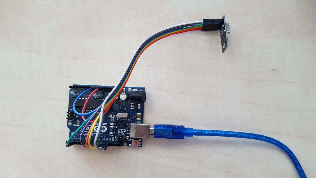
Setting up the Arduino NRF24Sniffer
Follow Ivo’s post http://yveaux.blogspot.nl/2014/07/nrf24l01-sniffer-part-2.html section Arduino sniffer sketch.
The only changes that you have to make in NRF24_sniff.ino are:
- Set the DEFAULT_RF_DATARATE on line 51 to RF24_250KBPS
- Comment out line 63 (#define BINARY_OUTPUT) to enable text output
If you find yourself in trouble, you can download the compiled project’s hex file here.
Use the following command to upload the hex file to your Arduino Uno
[code]
"C:\Program Files (x86)\Arduino\hardware\tools\avr/bin/avrdude"
-C"C:\Program Files (x86)\Arduino\hardware\tools\avr/etc/avrdude.conf"
-v -patmega328p -carduino -PCOM6 -b115200 -D
-Uflash:w:C:\dev\NRF24_sniff.cpp.hex:i
[/code]
When you fire up your Arduino it should generate some output like:

If no messages are showing up, you might check:
- Are there also messages ‘flying’ around, I forced this by resetting a Mysensor node
- Is the configured channel 76 in use in your environment, if not, change it to the channel you use in your Mysensors network
- Is the base address correct, you can find the Mysensors base address in your MyConfig.h file around RF24_BASE_RADIO_ID
- Are the NRF24L01+ pins connected correctly
Running the ASP.NET Core 1.0 website
Install .NET runtime if you are not on Windows
The package that I have created holds the Windows .NET executing environment, making it click and run on a Windows machine. If you run mac or linux you will need to install the .NET runtime 1.0.0-rc1-update1 for your machine:
https://docs.asp.net/en/latest/getting-started/installing-on-mac.html
https://docs.asp.net/en/latest/getting-started/installing-on-linux.html
It is basically as easy as running dnvm install 1.0.0-rc1-update1 as soon as you have dnvm (yes this is a Windows machine, but I guess the linux variant is not that different)

Download and run the application
Download and unzip version 1.0 of the published project here https://github.com/timdows/webpages/blob/master/MysensorsInformation/publish/MysensorsInformation1.0.zip?raw=true (19.1 MB)
From the approot folder, run the web command (web.cmd on Windows and web on linux/mac) to fire-up the application

From your favorite browser you should now be able to visit the webpage on localhost:5000 (make sure your firewall is not interrupting or anything)

Configuring the settings
Next you should some settings according to your environment
| Setting | Description |
|---|---|
| VeraIpAddress | The IP address of your Vera3 in your local network |
| MysensorsIpAddress | The IP address of your Mysensors gateway in your local network |
| MysensorsPort | The port where the Mysensors gateway is listening on |
| PortName | The serial port (COM) on your machine where the NRF24 sniffer arduino is connected to |
| BaudRate | The buad rate of the serial port of the NRF24 sniffer arduino |
| RfChannel | The RF channel, range between 0 and 127 |
| DataRate | The data rate, 0 = 1Mb/s, 1=2Mb/s, 2=250Kb/s |
| AddressLength | Promiscuous address length in bytes between 3 and 5 |
| BaseAddress | The base address to listen on |
| CrcLength | The package CRC length in bytes between 0 and 2 |
| MaximumPayloadSize | The maximum payload size in bytes between 0 and 32 |
| LookupMysensorsNodeViaVera | Enables the option to lookup Mysensors node information received via the serial port on the Vera |
These default settings can be modified in the appsettings.json file located in approot\src\MysensorsInformation.
Explanation of the data on the NRF24Sniffer page
Once you will visit the NRF24Sniffer page, the background process will start to capture data from the serial port.
The data can be shown in two formats, in a grid with the Mysensor device information or raw in a list form

The newly received rows are added to the top. It is possible to filter on every row or hide the column in general.
By default it shows the following table
| Group | Column | Description |
|---|---|---|
| N/a | DateTime | The time the message was processed formatted in HH:mm:ss.sss |
| NRF24Structure | TypeAndLength | Hidden, the original raw part that the sniffer recieved |
| NRF24Header | Timestamp | Hidden, from the original header part |
| NRF24Header | PacketsLost | Hidden, from the original header part |
| NRF24Header | Address | Hidden, from the original header part |
| NRF24Data | NodeAddress | Combined NRF24Structure.NRF24Header.Address and first two characters from NRF24Structure.Data |
| NRF24Data | PayloadLength | Length of the payload |
| NRF24Data | Pid | Packet identifier |
| NRF24Data | NoAck | Flag to suppress sending acknowledge packets on a per-packet basis |
| NRF24Mysensor | Last | Last node address |
| NRF24Mysensor | Sender | Sender node address |
| NRF24Mysensor | SenderVeraDevice | The name of the sender device in the Vera3 environment |
| NRF24Mysensor | Destination | Destination node address |
| NRF24Mysensor | DestinationVeraDevice | The name of the destination device in the Vera3 environment |
| NRF24Mysensor | Length | Length of payload, in bytes |
| NRF24Mysensor | Version | Version identifier of the mysensors protocol |
| NRF24Mysensor | DataType | Datatype of the payload |
| NRF24Mysensor | IsAck | Ack flag |
| NRF24Mysensor | ReqAck | Request ack flag |
| NRF24Mysensor | CommandType | Commandtype of the mysensors protocol |
| NRF24Mysensor | Type | Type of payload |
| NRF24Mysensor | Sensor | Sensor of the sender |
| NRF24Mysensor | SensorVeraDevice | The name of the sensor device in the Vera3 environment |
| NRF24Mysensor | Payload | The actual payload |
If you want to show the raw data from the serial port, you can select the show raw button.
This also displays the mismatched packages (e.g., the startup information of the Arduino program)

Explanation of the data on the MysensorListener page
This page basically shows the page from http://timdows.com/projects/realtime-data-from-mysensor-gateway-1-5-using-signalr-3-and-asp-net-core-1-0/
It has been given an upgrade to use ui-grid, making it possible to filter, and some refactoring of the code has been done in the background.

Understanding the raw NRF24 package information
In the first part of Ivo’s post (http://yveaux.blogspot.nl/2014/07/nrf24l01-sniffer-part-1.html) the message structure of the NRF24L01+ is explained. I will try to give a short recap.
All the messages from the Mysensors network are sent in the following structure (called ‘Enhanced Shockburst’). Note the 6 + 2 + 1 (9 in total) bits between the address and payload and the mandatory CRC field:

By default the Mysensors configuration forces a 2 byte CRC check.
The NRF24L01+ will discard any package that does not meet the CRC check, and we would like to capture also those packages.
To work around this Ivo came up with the idea to capture a different package format:

The result is that we wrap all data in the payload. This can mean that if the payload is actually 32 bites, we would lose 1 byte, 9 bits and 2 bytes of information:
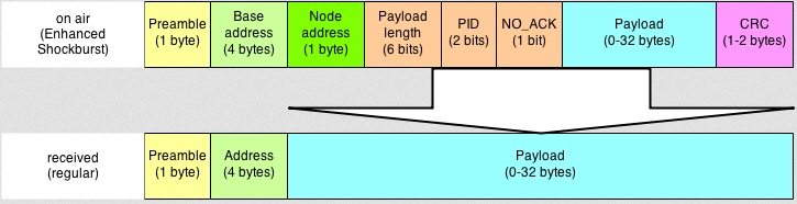
The loss of these information is to bad, but in my experience I have not seen many Mysensor network packages with more than 28 bytes of data.
To make sure that all data is presented in the correct form, the application takes care of shifting the bits into the correct place to get some sense out of the raw data.
TODO
- Calculate the CRC ourself as well to identify the amount of package loss due to CRC failures
(note, the receiving sniffer will not be able to identify a failed CRC check on the actual gateway, it will be limited to its own CRC information)
(note2, we can still identify CRC failures on the gateway if we notice that the same information from sender+sensor is send out more than once in a short timespan) - Go over all TODO’s in the code
- Add an option to save the captured data in an e.g. sqlite database
- Add the missing payload type conversions to the NRF24Mysensors class
C# and javascript code
All the code can be found on my github page: https://github.com/timdows/webpages/tree/master/MysensorsInformation
Most of the times this section is more prominent on the top, for this project the intentions are more to show what we can do with this hardware. That does not mean that the code is of any lower standard at all!
This application has been build as a MVC webpage on top of APS.NET Core 1.0.
It holds the following controllers:
- HomeController
Shows the settings and has an option to change some settings through the ui-grid on runtime - NRF24Controller
When called for the first time, a thread is started to process serial data from the NRF24Sniffer
It only returns an Index view - MysensorsController
When called for the first time, a thread is started to process information on the telnet connection of the MysensorsGateway
It only returns an Index view
Both, NRF24 and Mysensors, controllers spawn a thread that represents a SignalR hub:
- NRF24Hub
A task is responsible to inform the asynchronous code that data is available on the serial port. Every byte is then saved to a string.
If this string contains a \r\n the part before is splitted and processed into one or multiple messages.
Every message starts with a basic NRF24Structure that holds the DateTime, TypeAndLength, Header and Data.
If the header contains 18 characters, a header object is created from the NRF24Header class.
Next the NRF24Data object is created. Here some bitArrays help to retrieve the valid data from the complete data variable.
If the payload of the NRF24Data object is larger than 57 bits, a NRF24Mysensor object is created. Here as well, some bitArrays help to retrieve the specific data and store them into an object.
If the LookupMysensorsNodeViaVera option is enabled, the NRF24Mysensor information is used to find the responsible sender, destination and sensor device. - MysensorsHub
A TcpClient is responsible for capturing all data on the MysensorsGateway. Every byte is added to a variable and checked if a, or multiple, messages have been received. If so, these are processed and sent out as an MysensorsStructure object
The NRF24Helpers class holds static functions to process the data in the NRF24Hub.
A total of ten models are used throughout this application:
- MysensorsEnums
Holds six enums that define different defintions and types of messages going back and forward - MysensorsStructure
Holds the information of a complete message that can be captured via the telnet MysensorsGateway - NRF24Data
Holds the information of the data part of the NRF24Structure. Also has some public getters that provide human readable information about the bitArrays - NRF24Header
Holds the header information that is sent out by the NRF24Sniffer - NRF24Mysensor
Holds the information that the payload of a NRF24Data package can contain. Also has some public getters that give more human readable information of the object itself - NRF24Structure
Defines the NRF24 structure - SettingsDTO
DataTransferObject for the settings on the HomeController - VeraDevice
Holds details of a device in the Vera environment - VeraDeviceAltID
Holds specified information regarding the AltID variable for the Mysensors plugin on the Vera - VeraRoom
Holds the room information
The settings classes configured to be singletons (via startup.cs) except for the GeneralSettings that gathers the initial values from the appsettings.json file they all work the same:
- BaseState
Base class for the other state classes - GeneralSettings
Holds configurable information where the application can make requests (i.e., IP addresses) or listen on (i.e., serial ports) - MysensorsState
Holds the state for the MysensorsController - NRF24State
Holds the state for the NRF24Controller - VeraSettings
Upon creation, gathers all settings from the Vera3 environment. Is does a user_data request and processes the rooms and devices arrays from it into two lists
The javascript files, in wwwroot/js are Angular based and should be self explainable. The service.js holds a factory (based on the on/off/invoke pattern) that can be used to process SignalR information, it uses a timeout to prevent errors as most people use the $scope.$apply.
What could be better
- I have spent some hours (you can say more than a day) to get the CRC to work, for this version that was a nice to have point, so I concluded I wasted some time there
- In order to understand the dissector that Ivo created I found that the wireshark wiki/manuals are quite bad (or I just could not find what I was looking for, e.g., what are the arguments for tvb_get_bits8 or how is the tvb package constructed)
Also debugging a dissector was not easy, you had to add debug writeline information, build the dissector and run wireshark from a command prompt. Ahhh learned something there I could say
Comments are closed.