What is it? 
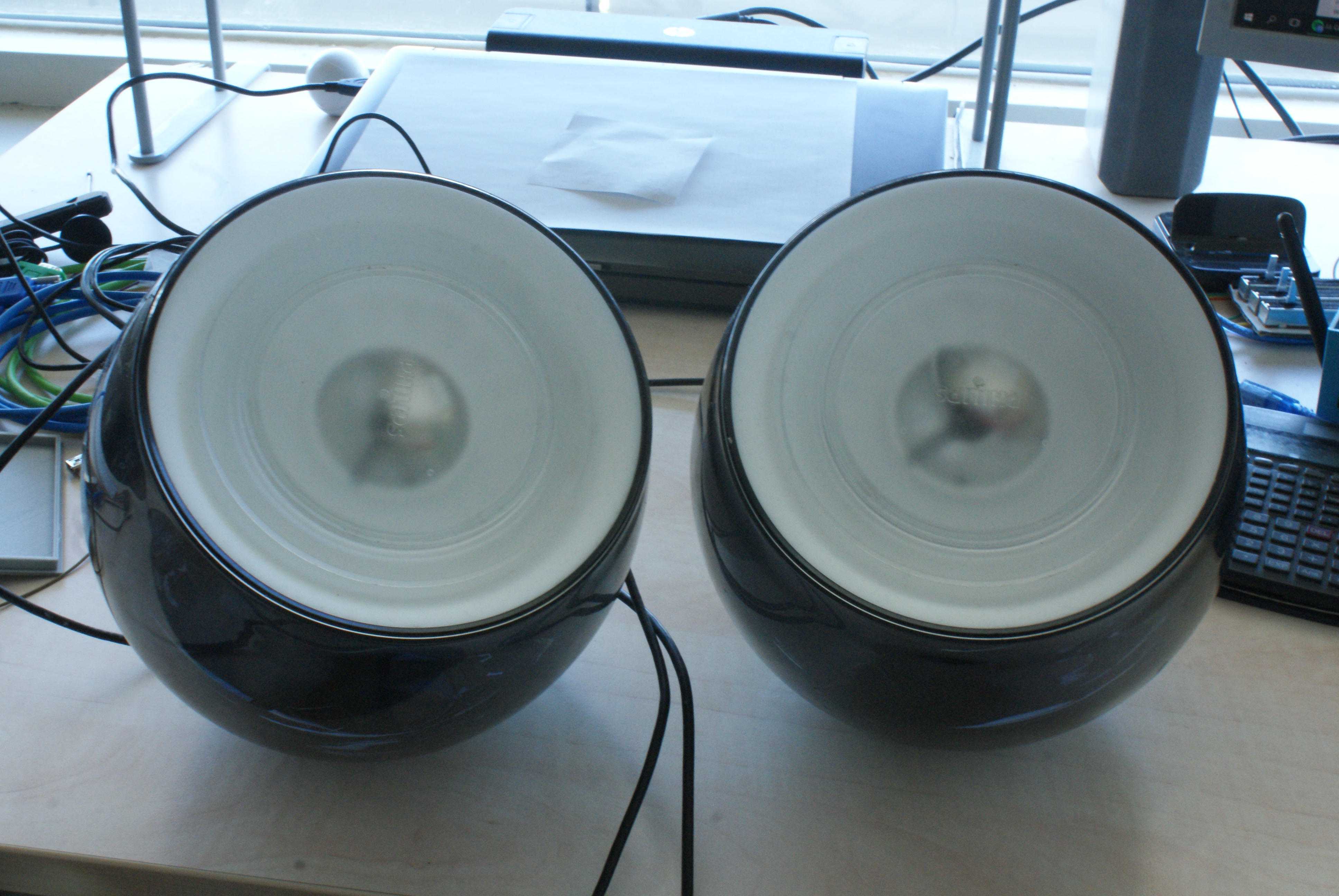
So I own two of these nice Philips Living Color gen2 lamps. They come with a remote and if you have two, you can pair them up and control them with the same remote (having both of the lamps outputting the exact same color).
Now I wanted this to be part of my domotica (Vera3 / MySensors) system, but it proved to be hard, or nearly impossible, to use the same remote protocol as the Philips lamps did.
The Gen1 protocol was reverse engineered by Jeroen (spritesmods.com) (I will find the exact link of it later) and some have made DIY remote controllers for these lights.
Soon, after some days going to this thing called Internet, I went on the path of destruction.
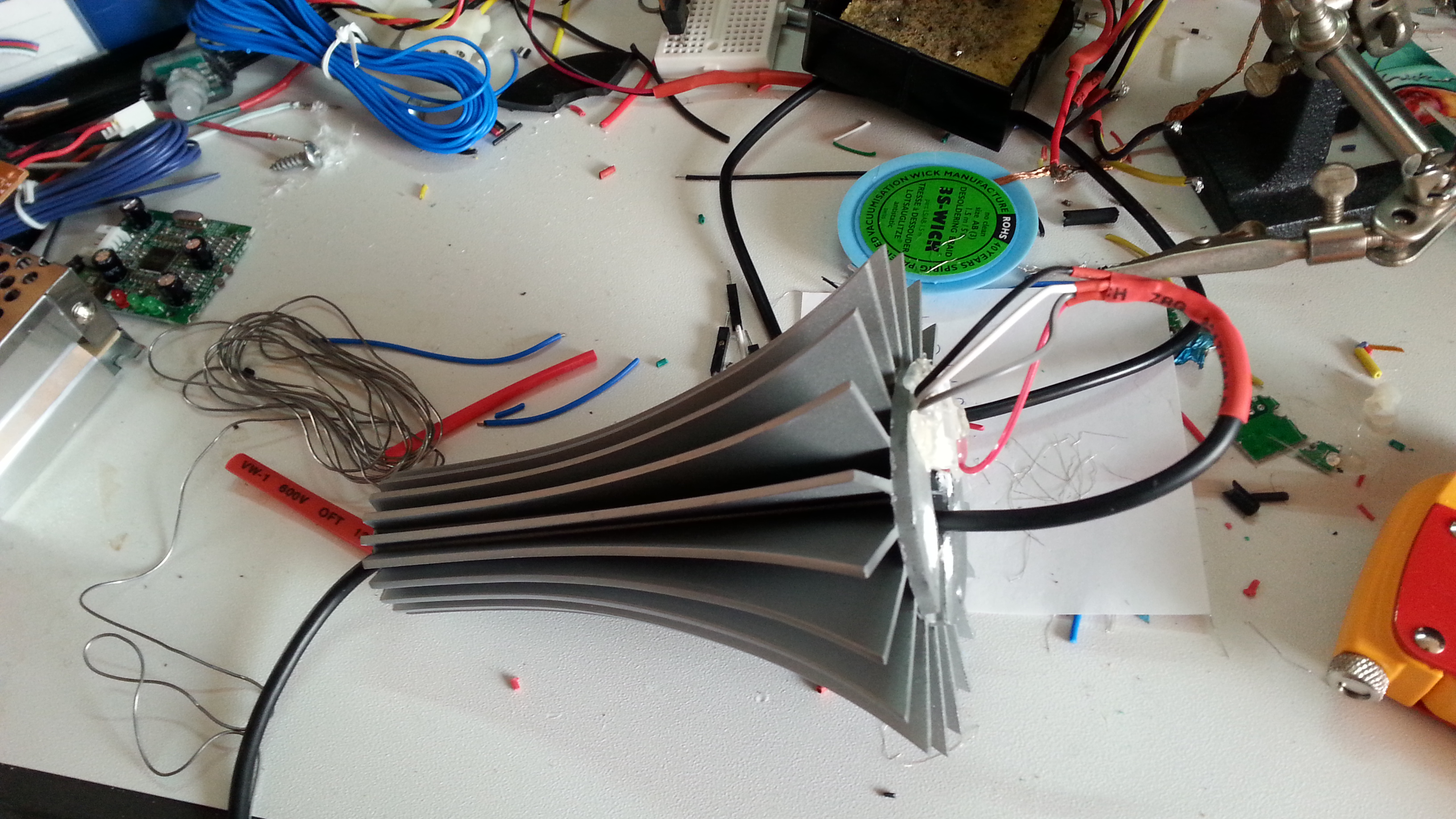
The goal was to use the inner body’s heat sink to cool down a 12V 10 watt RGB led, hook this up to a MOSFET and connect it all to an Arduino based MySensors sytem.
In my Vera3 environment this looks like

Eagle layout

The three MOSFETs are P16NF06’s.
Arduino code
https://github.com/timdows/AMD/tree/master/Philips living colors gen2 modification
philips_living_colors.ino sets up the MySensor environment and requests the latest value upon booting from the gateway.
In the loop, the 4 leds (Red, Green, Blue and All) are updated, upon an incoming message from the gateway the function incomingMessage is executed. This makes sure that the right color is changed accordingly to the message.
The class LedstripColor holds the current and the desired level of the led, and upon every update this is changed. The concept behind this class is of course a finite-state machine. It also makes sure that the gateway is in sync with the different objects.
End result


Some test results
Hooking them up to my cheep-ass multimeter, it showed me the following:
| Leds | Picture | Power drain | Watts used (at 12Volt) |
|---|---|---|---|
| Red |  |
1.31 Amps | 15.72 Watt |
| Green | 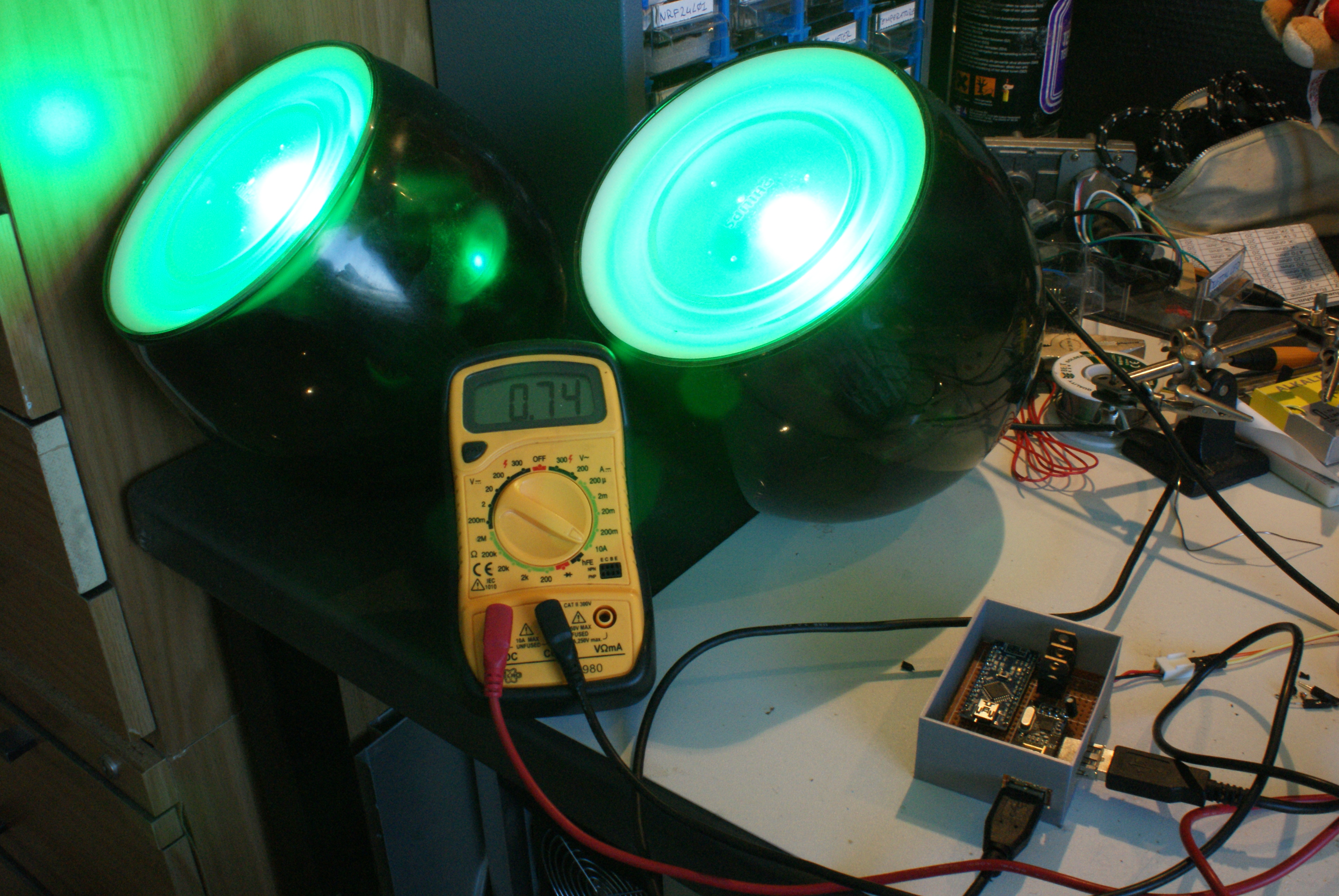 |
0.74 Amps | 8.88 Watt |
| Blue |  |
0.79 Amps | 9.48 Watt |
| Green + Blue |  |
1.00 Amps | 12 Watt |
| Blue+ Red |  |
1.36 Amps | 16.32 Watt |
| Green + Red |  |
1.39 Amps | 16.68 Watt |
| Red + Green + Blue | 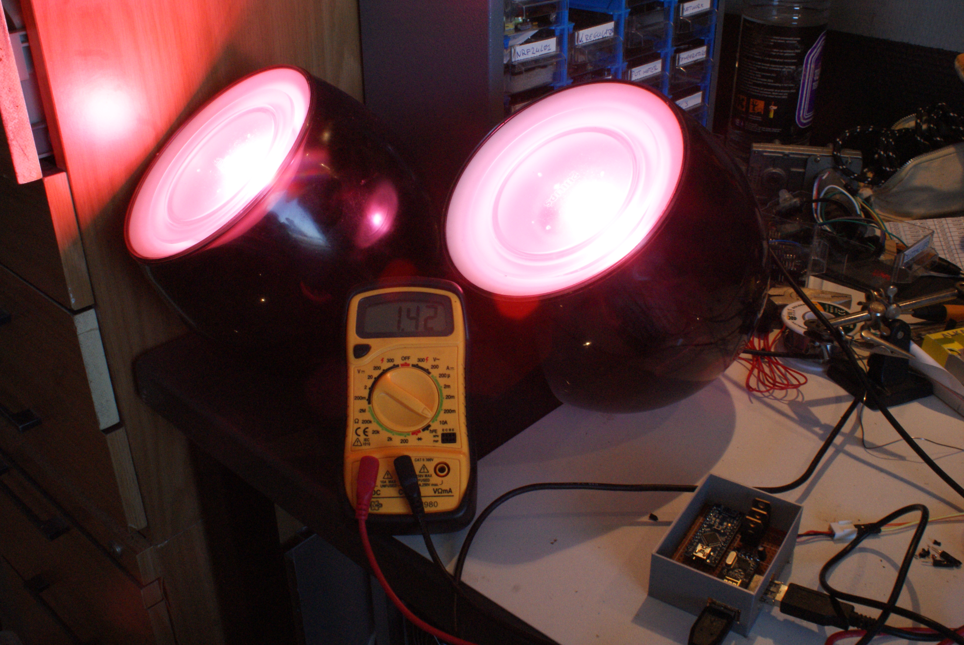 |
1.42 Amps | 17.04 Watt |
| All off |  |
0.02 Amps | 0.24 Watt |
If two leds use 17.04 Watt, than one uses 8.51 Watt. The Chinees company (i.e. ebay supplier) claimed 10 Watt, but I guess it only make up for 85.1% of it. In the end not that bad I guess.
3d print
Box drawn in tinkercad https://www.tinkercad.com/things/kZ8LGyqKAUW-usb-rgb-case

TODO
- After a while I noticed that when the colors had to change due to an incoming message, it kept flickering, like wanting to change to 40% and right after to 50%. Need to look into that somewhere in code.
- Make a top for the box or remove the Arduino’s power led as it gives a bit of undesired light.
Project costs in € or $
| Object | Price |
|---|---|
| Arduino Nano | $ 2.68 |
| 3x P16NF06 MOSFET | $ 4.79 |
| NRF24L01 | $ 0.86 |
| 3d print | € 5 |
| 2x 10watt RGB led | $ 3.40 |
| 2x Philips Living Color gen2 | ? |
| 12 volt 6 amps power supply | € 27.43 |
| Other materials | $ 2 |
| Total | $ 50.73 |
I had the Philips Living Colors for a couple of years now, bought them around the time they came out. My guess would be around 80 euro each (yes that is quite expensive).
What could be better
- Put a heat sink on the MOSFETs, or mount them to one of the fins of the inside of the lamp.
Normally I do not read article on blogs, however I wish to say that this write-up very pressured me to try and do so! Your writing taste has been surprised me. Thanks, quite nice post.