What is it? 
This box, called the orangebox, was created to solve a simple problem: Find which pin of a cable is connected to which pin on the other side of the cable.
The cables involved typically look like DB9 to RJ45, but can come with some other connectors as well.
An example schema of a cable can be like

In that example, two pins (4 and 6) on the DB9 female side are connected to pin 7 on the RJ45 side. Also on the RJ45 side pins 4 and 5 are connected to pin 5 on the DB9 side.
When you have multiple type of cables lying around, it gets hard to keep them apart.


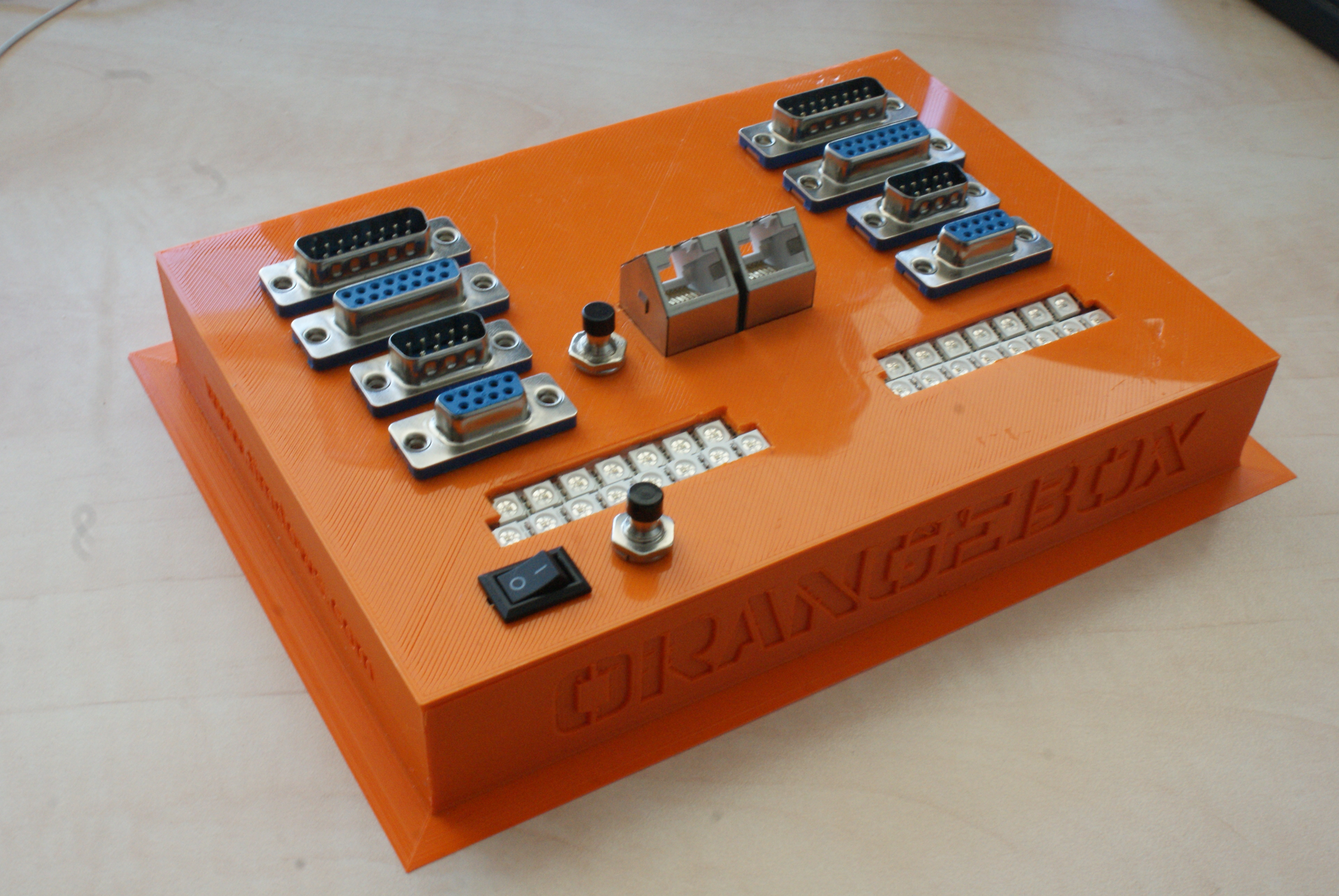
On the orangebox, 10 connectors are placed to make any kind of cable with an DB15, DB9 and RJ45 connection testable.

On both sides of the cable LEDs will indicate the connections in the cable making it clear in one view which connections exist between the pins.
Eagle layout (rev2)

In this schematic overview, the mux part is depicted only once.
The DB15, DB9 and RJ45 connectors are not drawn at all.
Arduino code (rev2)
https://github.com/timdows/AMD/tree/master/Orangebox
The code consists of 4 files, it was split to improve readability (no fancy classes or stuff like that).
cable_tester.ino loops through the mux left and then checks if there is a connection to the right side by looping through the right mux. If an connection is found, it is stored in a two-dimensional array. Upon every connection found, it also checks if there was already an connection to make sure the pin will get the same led color as the previous found connection.
When no pin is connected, every 5 seconds the mode will be displayed on the led strips.
If the mode button is pressed, the current mode will be displayed. When the button is pressed when the mode is shown on the led strips, the mode will change to the next mode and displays the new mode on the led strips.
setLedLeft.ino and setLedRight.ino both have 3 parts, for DB15, DB9 and RJ45. Every part makes sure the correct led is addressed for the mode the box is in.
setMode.ino creates a 4 byte array that displays the different modes available on the led strips.
The nine modes are
- DB15 to DB15
- DB15 to DB9
- DB15 to RJ45
- DB9 to DB15
- DB9 to DB9
- DB9 to RJ45 (Mode it is in after startup)
- RJ45 to DB15
- RJ45 to DB9
- RJ45 to RJ45


End result rev1
The first version was created around a breadboard in order to easily make changes.


End result rev2
This version was created to hold different versions of the DB9 and DB15 connectors I found on ebay.
It is also less high, as the breadboards made place for DIY protoboards.
Board 1 holds the arduino and two headers. One for the power input and the other for the communication with the mux boards.
Board 2 is created double, for the left and the right side of the box. It holds a CD74HC4067E multiplexer.


3d print (rev2)
Box drawn in tinkercad https://www.tinkercad.com/things/41Lo20WulWx-orangebox-rev2

Top drawn in tinkercad https://www.tinkercad.com/things/7C7LAMVSVuQ-orangebox-rev2-top

Documentation with the project
As I encountered some issues, the usual ones that you fuck-up the pin count of a connector, I created an overview sheet to go with it.
pin layout sheet.ods
Don’t forget that the connectors viewed in this documents, are the connectors on you cable and NOT the connectors on the orangebox!
TODO
- It is possible that a pin is connected to another pin on the same side of the connector. To detect this, another 2 mux’s are needed to identify these connections.
- Create a led next to each type of header (DB15 / DB9 / RJ45) that indicates the mode the box is in.
- Find nice led colors for the DB15 pins, as I found out that some colors on the leds look a lot the same.
Project costs in € or $
| Object | Price Rev1 | Price Rev2 |
|---|---|---|
| Arduino Pro Mini 5v | $ 1.92 | |
| Arduino Nano | $ 2.68 | |
| 2x CD74HC4067E | $ 2.28 | $ 2.28 |
| 4x Adafruit NeoPixel Stick | $ 24.76 | |
| 4x WS2812 5050 RGB LED Lamp Panel Module 5V 8-Bit Rainbow LED Precise | $ 8.36 | |
| DB15 connectors | $ 6.23 | |
| DB9 connectors | $ 15.36 | $ 4 |
| RJ45 connectors | € 7.79 | € 7.79 |
| Battery | ? | |
| 3d print | € 60 | € 26.97 |
| Other materials | $ 5 | $ 2 |
| Total | $ 124.92 | $ 63.49 |
What could be better
- Don’t try to put things to fast in a 3d print, find the parts first, order them and make a 3d drawing around those parts.
- Look further for parts as they might come cheaper (e.g. see the difference in the price between rev1 and rev2).
Comments are closed.